New feature for PLC-testing: Overview of allocated bits
New feature for PLC-testing: Overview of allocated bits
When you’re testing a PLC in Physics Mode, it can be useful to have a good overview of the bits you’ve already allocated.
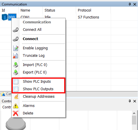
With most communication protocols, you can right click on the PLC connection and click “Show PLC Input” or “Show PLC Output”, as shown in the screenshot below.

Earlier all the numbers in these windows were the same color. That meant that it could be a bit difficult to figure out which bits were already allocated, and which weren’t.
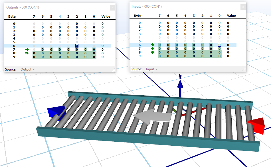
With this new feature that is much easier. When you open “Show PLC Input” or “Show PLC Output”, the bits that you have allocated are highlighted.

And when you click on a specific bit, all other bits that belong to the same component are highlighted in green, while the component and property relating to the allocated bit is shown in the button of the window. In case of double allocation of the memory, the number will be highlighted in red, as double allocation isn’t normally intended.
If you for instance work with complex motors with lots of I/O (as shown in the screenshot below), this feature will give you a much better overview over your allocated bits and their correlation.

This feature functions with the latest Experior version (6.0.15833) and with the following communication protocols:
- Fetch/Write
- S7 Functions
- EtherNet / IP – CIP
- Modbus TCP
- Serial Port
- XCom
